
Basics of
Electricity
1.
Electricity is a form of energy in which electron flows in a conductor from
higher to lower potential in the same manner as water flows from higher to
lower level. The flow of electricity can be detected by one or more of the
following effects:-
(a)
Heating Effect.
A flow of electricity will generate heat in the conductor through which it
flows. This property is made use in lamps, Electric heaters etc.
(b)
Chemical Effect. A flow of
electricity through certain solution will split the solution into its various
constituents. This property is made use of electroplating, Electrical
batteries.
(c)
Magnetic Effect. A flow of
electricity through a conductor causes a magnetic field to be setup around the
conductor. This property is made use in generators, motors, relays, solenoids
and actuators.
(d)
Physical Effect. Our
body is a good conductor. Current can easily pass through it. When the
body touches a conductor carrying current, current flows through our body to
ground (Earth) and body experiences a shock.
2.
The following are few sources of electricity:
(a) Battery.
This stores electrical energy in the form of chemical energy and when required
it gives off electrical energy. Batteries are used as a power source for
various electrical appliances like radios, cell phones etc.
(b) Generator.
It is a machine, which converts mechanical energy into electrical energy i.e.,
when the machine is driven by a prime mover, it produces electrical energy.
This is one of the ways of generating commercial power.
(c) Thermo
Couple. Two dissimilar metallic wires
joint together at one end develop an EMF when there is temperature difference
between their junction points. This is used to read temperature of jet engine
and furnaces. e.g., hot wire meter.

Fig 1 Copper-Iron
Thermo-Couple
(d) Solar
Energy. The
energy obtained from the sun is called solar energy. It is a natural
source of energy available in abundance. Solar cell or a photo voltaic
cell is used to convert solar energy into electrical energy by making use of
photo voltaic effect. Devices which use solar energy to produce electricity are
solar cell which are used commonly in calculators, watches, etc.
3.
Current. The free
movement of electrons in a wire of conducting material like copper is known as
electric current. An electric current usually termed as ‘current’ is nothing
but flow of electrons or a flow of charge from higher potential to lower
potential. If a charge Q passes across a conductor in time T, and current I is
said to have flown then:
I
= Q/T
Where,
Q
- Charge measured
in Coulombs
T
- Time in sec
Hence the
current I is measured in Coulombs per second
Thus, Ampere =
Coulombs/ second
4.
Resistance. The resistance of a conductor is
the opposition offered to the flow of current through the conductor. The
unit of resistance is Ohm. The temperature remaining constant, the current
flowing through a conductor is directly proportional to the potential
difference between the two ends of the conductor. V / I = R where R is a
constant, known as resistance of the conductor.
(a)
Ohm. It is that resistance, which permits a
current of one ampere to flow when a potential difference of one volt is
applied.
(b)
Resistance of a conductor is directly proportional to the length of the
conductor and inversely proportional with its cross sectional area and specific
resistance of the conductor.
5.
Voltage.
Electrical pressure, which causes an electric current to flow through a
complete electrical circuit or the force which results from the conversion of
heat, chemical or mechanical energy into electrical energy is known as the
Electro motive force (EMF).Unit of EMF or potential difference (PD) is
volt. The PD between two points in an electric field is said to be one
volt if one joule of work done in moving a coulomb of charge from one point to
the other. Relationship between Q and V is:
V
=
Q/C
where C is the
constant known as Capacity and V is the potential difference.
6.
Capacitance.
It is the ratio of charge to potential. It is defined as the charge required
raising its potential to unity. Unit of capacitance is Farad.
7.
A capacitor is a device, which increases the capacity without increasing the
dimensions in an apparatus for condensing a large quantity of electricity on a
comparatively small surface. It consists of two conducting surface divided by a
layer of an insulating medium by dielectric. (Fig 2). The conducting surface
may be in the form of either circular (or rectangular) plates or spherical or
cylindrical shapes. The purpose of capacitor is to store energy by
electrostatic stress in di-electric.

Fig 2 Capacitor
8.
Inductance. The property of the coil due
to which it opposes any increase or decrease of an alternating current or flux
through it is known as inductance. The unit of inductance is Henry and denoted
by capital letter “L”.
9.
Resistance in Series.
When two or more resistors are connected in series, the total resistance of the
circuit will be the algebraic sum of individual resistors. Let three resistors
R1, R2 & R3 are connected in series. Refer fig. 3. The total resistance
is:-
R
=
R1+R2+R3

Fig 3 Resistances in Series
10.
Resistance in Parallel. When the
resistors are connected in parallel, the inverse of their effective resistance
is equal to the sum of the inverses of individual resistance. Let R1,
R2 and R3 are connected in parallel as shown in Fig4.
Then,
1/R = 1/R1+1/R2+1/R3
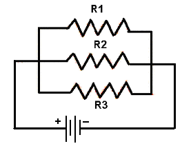
Fig 4 Resistances
in Parallel
11.
Series and Parallel Resistance in Combination.
A circuit in which some resistances are joined in series while others are
joined in parallel is known as series parallel combination. (Refer Fig. 5)

Fig 5 Series
and Parallel Resistance
Transformer
12.
Transformer is a static piece of device by means of which electric power in one
circuit is transformed to electric power of same frequency in another circuit.
A transformer is either step-up or step down type. It consists of three main
parts:
(a) An Iron core which provides a circuit
of low reluctance for an alternating magnetic field created by
(b) Primary winding which is connected to
the main power source.
(c) A secondary winding which
receives electrical energy by mutual induction from the primary winding and
delivers it to the secondary winding. (Refer Fig 7)
13.
When an alternating voltage is applied to the primary winding an alternating
current will flow and by self-induction it will establish a voltage in the
primary winding, which is opposite and is almost equal to the applied voltage.
The difference between these two voltages will allow just enough current to
flow in the primary winding to setup an alternating magnetic flux in the core.
The flux cuts across the secondary winding and by mutual induction a voltage is
established in secondary winding.
Fig 6 Simple
Transformer
14.
Mutual Induction. It is the ability of a coil or
circuit to produce EMF in near by coil by induction, when the flux in the
circuit of the first coil changes. This can be reciprocal transformer.
15.
The following are the types of transformer:
(a) Step up
(b) Step down
Fig 7 Step
Up & Step Down Voltage Transformer
16.
Electrical Symbols.
Some important electrical symbols are given below:


Fig
8 Electrical Symbols
Ohm’s Law
17.
The most important law applicable for study of electricity is Ohm’s Law. This
law outlines the relationship between voltage, current and resistance in an
electrical circuit. Ohm’s experiments show that whenever electric current is
flowing through a conductor the following three factors are present:
(a)
The pressure or potential difference (V) across the conductor (measured in
volts) causing the current to flow.
(b)
The resistance (R) of the conductor (measured in Ohm) which must be overcome.
(c)
The current strength (I), which is maintained in the conductor (measured in
Amp) as a result of potential difference overcoming the resistance.
18.
There exists a definite and exact relationship among the three quantities
involved. This is known as Ohm’s Law.
19.
Definition. In a DC electrical circuit,
the ratio between the applied potential difference (V) and the current (I)
flowing is constant at a constant temperature. That is V/ I is constant,
and this constant is the resistance of the conductor. The relationship between
EMF, current and resistance is expressed by "Ohm's Law" which states
that the current in a circuit is directly proportional to the potential
difference and inversely proportional to the resistance of the circuit. Thus,
other factors remaining constant, if the potential difference is doubled, the
current is doubled, if the resistance is doubled, the current is halved; Ohm's
law can be expressed as an equation:

20.
Application. The applications of Ohm’s law are as
follows:
(a) This law is applicable to all DC
circuits.
(b)
In a modified form it is applicable to AC circuits also provided account is
taken of the induced EMF resulting from the self-inductance of the circuit and
distribution of the current in the cross section.
Kirchoff’s
Law
21.
A German physicist GR Kirchoff elaborated on Ohm’s Law and developed two
statements that are known as Kirchoff’s Laws for current and Voltage. An
understanding of these the laws enable the aircraft technician to gain a better
understanding of the behaviour of electricity. Using Kirchoff’s Law, it is
possible to find the following:
(a)
The current in each branch of a network circuit, when both the resistance and
EMF in each branch are known.
(b)
The EMF in each branch when both the resistance and the current in each branch
are known.
22.
These laws are stated as follows:
(a)
Current Law or Point Law.
In an electrical network, the algebraic sum of the current meeting at a point
(or junction) is zero. In simple means that the amount of current leaving a
junction is equal to the total current entering to that junction. i.e., S
I = 0. Consider the case of a few conductors meeting at a point as shown in
Fig1.12, let I1, I4 current of a conductor entering at
the junction and I2, I3, I5 current of
conductor leaving at the junction. Assuming the incoming current positive and
outgoing current negative. Next applying current law, algebraic sum of current
meeting at a junction is zero.

Fig
9 Various Conductors Meeting at a Junction
I1
+ (-I2) + (-I3) + I4 + (-I5)
= 0
Or I1 + I4
-I2 -I3 -I5 = 0
Or I1 + I4
= I2 + I3 + I
Or
incoming currents = outgoing currents
Or S I = 0
(b)
Mesh Law or Voltage Law.
It states that the algebraic sum of the product of current and resistance
in each of the conductors in any closed mesh (or path) in a network plus the
algebraic sum of the EMF in that path is zero. In other words:
S IR + SEMF= 0
Principle
of Electro Magnetism
23.
Electro Magnetism.
When a magnetic material like an iron bar placed inside a long coil of
insulated wire carrying a strong current, the iron bar will behave like a
magnet. The magnet made by this (electric) method is known as electromagnet and
this phenomenon is known as electromagnetism. It is capable of raising heavier
load than the permanent magnet.
24.
The magnetic field around the conductor in which the current is flowing all the
lines shown would appear more as continuous in cylindrical or circle form
around the conductor as long as current flows in the conductor. The line of
force remains around it as it is shown in Fig 6. If a small current flows
through the conductor there will be a

Fig 10 Magnetic
Lines Around the Conductor
line of force
extending out to circle A. If the current flow will increase its size to circle
B and a further increase in current will expand it to circle C as the original
line of force expands from circle A to B a new line of force will appear at
circle A as the current flows increases the number of circles of force
increases expanding the outer circles farther from the surface of the current
carrying conductor. If the current flow is steady non-varying direct current,
the magnetic field remains stationary. When the current stops the magnetic
field collapses and the magnetism around the conductor disappears. These are
used in electrical devices like generator, motor, relays, etc.
25.
Faraday’s Laws of Electro Magnetic Induction.
In earlier discovery it was observed that an electric current flowing through a
conductor creates a magnetic field around the conductor. There was a
considerable scientific speculation about whether a magnetic field could create
a current flow in a conductor. Michael Faraday discovered a relationship that
how an electric current can be created by a magnetic field. He has
formulated two laws. They are:
(a)
First Law. Whenever the
number of magnetic lines of force linking with an electric circuit is changed,
an EMF is induced in the circuit.
(b)
Second Law.
The magnitude of this induced EMF is directly proportional to the rate of
change of flux linking. Suppose
the total flux in the circuit
is Ǿ and induced EMF is E then:
E α d Ǿ/ dt.
26.
Fleming’s Rule. Fleming has
given two rules. i.e. Fleming’s right hand rule and Fleming’s left hand rule.
Fleming’s right hand rule is used to know the direction of current in case of
generator, where as Fleming’s left hand rule is used to know the direction of
rotation of motor:
(a)
Fleming’s Right Hand Rule.
Extend the thumb, fore finger and centre finger of the right hand, so that they
are at right angle to one another. If the fore finger (f) points in the
direction of field and thumb (m) in the direction of motion, then centre finger
(c) will indicate the direction of induced EMF in the circuit. (Refer Fig 12)

Fig 11 Fleming’s Right Hand Rule
(b)
Fleming’s Left Hand Rule.
Ref fig 12 Stretch the fore finger, centre finger and thumb of the left hand mutually
at right angle to each other. If the fore finger points in the direction of
field and center finger in the direction of current, then thumb will indicate
the direction of rotation of motor. (Refer Fig 13)

Fig 12 Fleming’s
Left Hand Rule

Fig 13 Series
DC Circuit
27.
In series DC circuit the resistance R1, R2, R3
connected in series and applied emf across the circuit is 30V. The total
resistance i.e., the sum of R1, R2, R3 = 5 +
10 + 15 = 30 W.
Since, the
applied voltage = 30 V.
Using equation
ohm’s law I = V/R = 30/30 = 1 Amps
The voltage drops across R1, R2, & R3
are
V = IR1 + IR2 + IR3 = 5 + 10 + 15 = 30 V.
Thus sum of voltage drop across the circuit is 30 V.
= applied voltage is 30
V.
Hence, the current in closed mesh is 0.
28.
Electric Network. It is a combination of
various electric elements connected in any manner.
29.
Circuit. It
is a conducting path through which an electric current either flows or is
intended to flow.
30.
Purpose & Principle of Generator.
A generator is a machine, which converts mechanical energy into electrical
energy, when driven by a prime mover. Generator works on the principle of
Faraday’s laws of electromagnetic induction. Its direction of induced
current is found by Fleming’s Right hand rule.
31.
Purpose & Principle of Motor. Electric
motor is a machine, which converts electrical energy into mechanical energy
when input supply is given by any source. Its action is based on the
principle that when a current carrying conductor is placed in a magnetic field,
it experiences a mechanical force whose direction is given by Fleming’s left
hand rule and whose magnitude is given by F = BIL Newton.
Where,
F
=
Force
B
= Flux density
I
= Current
L
= Length of the
conductor.
32.
Difference between Generator and Motor.
Generator |
Motor |
||
|
(a)
|
It converts
mechanical energy into electrical energy when driven by prime mover.
|
(a)
|
It converts
electrical energy into mechanical energy, when input supply is given by any source.
|
|
(b)
|
It works on
the principle of Faraday’s Law of electro magnetic induction and its
direction of induced current (e.m.f) is found by Fleming’s right hand rule.
|
(b)
|
It works on
the principle “when a current carrying conductor placed in a magnetic field
it experience or produce a mechanical force whose direction of rotation is
found by Fleming’s Left hand rule.
|
33.
Relays. It
is an electrically controlled device that opens and closes electrical contacts
to effect the operation of other devices in the same or another circuit. Relays
are usually used for low current switching application. The part of relay
attracted by the electromagnet to close the contact points is called armature.
and the movement of the armature either closes or opens the contact points. In
some cases the electromagnet operates several sets of contact points
simultaneously. It can be used up to 5kw.
34.
Solenoid. A coil of wire wound in
the form of a spiral is called a solenoid. When current is passed through a
solenoid, a magnetic field is produced. The direction of the magnetic
field around a current carrying solenoid can be found by using grip rule.
(Refer Fig 14). Grip the solenoid in the right hand, wrapping the fingers
around it and the direction of fingers is, the direction in which current is
flowing. Extension of thumb in the direction of the axis of coil indicates the
end having north polarity.

Fig 14
Grip Rule Diagram

Fig
15 Solenoid
35.
Switches. A switch can be defined
as a device for closing and opening (making or braking) an electric
circuit. It usually consists of one or more pairs of contacts made of
metal or metal alloy, through which an electric current can flow when the
contacts are closed. The switches can be manually operated, electrically
operated or electronically operated. The manual switch is usually operated by
either a lever or a push button. Electrically operated switches are called
relays or solenoids.
36.
Switches are designed with varying number of contacts to make suitable for
controlling one or more electric circuit. The switch used to open and close a
single circuit is called Single Pole Single Throw (SPST) switch (Fig 16).
A switch designed to turn two circuits on and off with a single lever is called
two-pole or Double Pole Single Throw (DPST) switch (Fig 17). A switch
designed to route current to either of two separate circuits is called Single
pole double throw (SPDT) switch (Fig 18). Double throw switches can be designed
with or without a centre OFF position. The three-position switch (one
containing a centre OFF position) could be used when it is necessary to connect
a wire to a choice of two circuits or disconnect it from both is known as
double pole double throw (DPDT) switches (Fig 19).Two-position double pole
double throw switches contain no OFF position. Switches available in different
configurations are as follows:
Fig 16 SPST

Fig 17 DPST

Fig
18 SPDT

Fig 19 DPDT
(a)
Toggle Switch.
These are normal on/off switches.
(b)
Rotary Switch.
It takes the place of several switches when the knob of the switch is rotated
switch opens one circuit and closes another. E.g., Ignition switches, Voltmeter
selector switches, fan regulator etc.
(c)
Push Button Switch.
It is spring loaded and designed for momentary contact, used to operate compressors,
motors and aircraft fire bottle operation etc.
(d)
Micro Switch.
It will open or close a circuit with a very small movement of the tripping
device (1/16 inch or less). It is also known as snap action switch is a generic
term used to refer to an electrical s/w that is able to be actuated by very
little physical force through the use of tipping point mechanism. Micro
switches are usually push button switches. They are used primarily as limit
switches to provide automatic control of landing gears, actuators, motors, etc.
37.
Protective Devices.
A common cause of circuit failure is due to a short circuit. The danger
in short circuit is that an excessive amount of current may flow through
limited portions of the circuit, causing wires to overheat and burn off
insulation. Many fires are caused by short circuit, but this danger is largely
overcome by installation of protective devices, such as fuses, circuit breakers
etc.
(a)
Fuses.
A fuse is a strip of metal having a low melting point. It is placed in a
circuit in series with load so that load current flows through it. When
current flowing through it exceeds the capacity of fuse, the metal strip melts
and breaks the circuit.
(b)
Circuit Breakers. A circuit breaker
serves a purpose similar to that of a fuse; however the circuit breaker can
usually be reset after the circuit fault has been rectified. There are
several types of circuit breakers in general use in aircraft systems.
Aircraft
Electrical System
38.
The first application of electricity in aircraft was in the form of the Engine
Ignition System. This did not raise any power supply problems because
self-contained magnetos supplied the current needed for ignition. For a long
time there was no much use of electricity in aircraft, except that which was
needed for simple lighting and communications. As and when the role of aircraft
was broadly extended, the flying machine was improved in construction and in
other aspects. Due to this, the need for a separate electrical system became
inevitable in a modern aircraft.
39.
For aircraft electrical system, the fundamental consideration was in
determining the type and capacity of the system, the kind of generators and
generator drives to be used based on the principle thing, which should be done
electrically. The choice of the electrical system and its capacity is made on
the following considerations:
(a)
Aircraft role and environment.
(b)
Type of apparatus existing in aircraft.
(c)
Time scale.
(d)
Available ground facilities.
(e)
Aircraft safety requirements.
(f)
Weight of installation.
(g)
Total capacity of system.
40.
Storage Batteries.
Storage batteries serve the following functions as:
(a)
To provide supply to starting accessories at the time of starting.
(b)
It is used for aircraft starting (internal start) in case of external supply is
not available.
(c)
It is meant for standby source in case DC Generator fails in Air.
(d)
It is used to provide supply to ignition coils in case engine RPM surged during
flight. i.e., it is useful for relighting the aircraft engine in air.
41.
Maintenance of Storage Batteries.
The following checks are to be carried out to keep the batteries in fully
serviceable conditions:
(a)
Visual Examination.
Container cover is to be opened and external damage, if any, are to be
checked. The tightness of all nuts and connecting bus bar strips between cells
are to be checked. The level of electrolyte as per the markings, the date of
capacity test carried out and life expiry date are to be checked.
(b)
Routine Charging. The batteries are to be sent for routine
charging when any cell voltage falls below normal value.
(c)
Capacity Test.
This test is carried on the following occasions:
(i) At the time of initial
build up.
(ii) When capacity falls below
the normal value.
AC &
DC Generators
42.
In most of the earlier aircrafts, the aircraft electrical systems were planned
on a basic DC power source. For DC power supply DC generators were used and for
AC power requirements Invertors and alternators were used. With increased power
requirements the basic DC power supplied by generators were found inefficient
due to some related problems like commutation and high altitude operations. To
overcome these difficulties all the modern aircrafts are now using AC as basic
power source, generated by alternators.
43.
In modern aircrafts, the latest aircraft electrical system has become 200V or
208V AC three phases 400 cycles/ second. The main AC is produced by one or two
AC generators and DC power is supplied by transformer and rectifier unit (TRU).
The battery is used as a stand by DC power and static Invertors are used as
emergency AC power source.
44. AC Generator.
AC Generator is used to produce an alternating current. In the AC
generator slip rings with brushes used to collect the AC supply from the AC
generator. Its application based on set of winding. If it has one
set of winding it is called single-phase generator. It is used for low output.
If a set of three winding is used then it is called three-phase generator, used
to get large output. Their connections are given in star or delta fashion.
(Refer Fig 20).

Fig 20 AC Generator
45. Types of AC Generator.
The Following are the types of AC generators:
(a) Rotating
armature type.
(b) Rotating field
type.
46. DC Generator.
Dc Generator is used to produce direct current. by replacing slip rings in AC
Generator with split rings (commutator),alternating current is changed as
direct current in the external circuit.
Electrical Components Used in Aircraft
47.
Starter Generator. It is a DC machine with compound
excitation used in aircraft. It is designed for starting the engine and
then to serve as a DC supply source to the aircraft and charge the storage
battery. The main aircraft engine drives the starter generator.
48.
Ampere Hour Meter.
An integrated ampere-hour meter serves to indicate the capacity of the storage
batteries. In AH
49.
Over Voltage Protection Unit. This unit
is intended to protect the generator from overloading due to increased voltage
in case of regulator failure. When the voltage increases beyond a safe value
this unit cuts off the supply of differential relay and thereby disconnecting
the generator from the mains.
50.
Centralised Warning Panels. The
centralised warning system provides the pilot with immediate indication on
failures or emergency conditions in certain system of aircraft, which could be
hazardous to pilot and aircraft. It incorporates two types of warning,
designated as primary and secondary:-
(a)
Primary Warnings. These are dangerous warning as main
hydraulic pressure failure, fire in engine compartment, DC generator failure
and fuel reminder etc. Primary warning lights the red warning lamps on the instrument
panel and red caption on the centralised warning panel, to identify the
particular warning source.
(b)
Secondary Warnings. It
lights up the amber captions on the centralised warning panel to identify the
particular warning source and initiate flashing of the attention lamp. These
warnings do not produce an alarm as RT failure, undercarriage warning.
51.
Invertors. It is a device which
converts 28V DC into 115V, 400 Hz, 1f / 3f AC. These are divided into two
types as:-
(a) Rotary
Invertors. It is a combination of DC motor and AC
Generator having separate armature and rotor winding, both sharing a common
field. It is also called mechanically operated invertor, i.e., dc motor
driving an ac generator. These are available in Single phase or three
phase type. These are being used in old version aircrafts.
(b) Static
Invertors. The purposes of static
invertors are same as rotary invertors i.e., to convert dc supply into ac
supply. It is also called electronic invertors because its principle is
based on Silicon Control Rectifier (SCR). These are used in modern aircraft,
due to quicker in response, no radio interference, power consumption is less,
and compact in size, weight is less. It provides supply to various
aircraft loads as Radio, Radar, Autopilot instrument etc. It is also used as
standby source in case of aircraft supply failure.
52.
Carbon Pile Voltage Regulator. This unit maintains
the generator voltage constant at prescribed value, when load or speed of
generator is changed.
53
Methods of Voltage Regulation. There are following
methods used for voltage regulation:
(a) Two Coils
Method.
(b) Negative feed
back method.
(c) De-compounding
method.
(d) Equivalised
voltage control method (EVC).


+ comments + 4 comments
Hi,
Nice! post
Thank you for sharing Basic Electrical Engineering
you must add some images on your post.
Very detailed information is given for Basic Electrical Engineering - Introduction to Electrical, you can also Learn Basic Electrical Engineering 1 with Our Adaptable Online Videos Course Materials Video Lectures on Electrical Engineering from Superior Faculty.
Very effective
Such a nice blog and I appreciate your all efforts about your thoughts. It’s really good work. well done.
power strip with surge protector